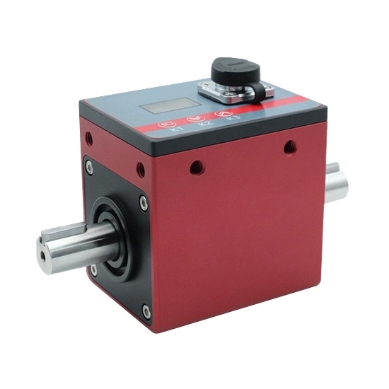
Digital torque sensor integrates non-contact rotary torque sensor and rotary/speed/power meter in one, maximum custom net weight 16kg, designed for bidirectional torque measurement.
- Torque measurement range 0.1/1/5/20/100/800/1000/3000/5000/10000 Nm
- OLED display for rotary/speed/power in real time
- 0.1%FS non-linearity, 0.03%FS hysteresis
- Output signal ±5V, 0-10V, 4-20mA, RS485
- Maximum speed 15000rpm
Unit: mm
1. Dimension for capacity 0.1~5 Nm (Basic Thread: 53*53, 4-M8 depth 10)
2. Dimension for capacity 10~100 Nm (Basic Thread: 53*53, 4-M8 depth 10)
3. Dimension for capacity 200~300 Nm (Basic Thread: 53*53, 4-M8 depth 10)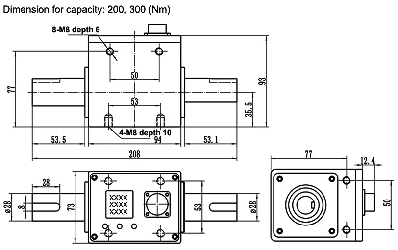
4. Dimension for capacity 500~800 Nm (Basic Thread: 75*60, 4-M8 depth 12)
5. Dimension for capacity 1000~5000 Nm (Basic Thread: 75*60, 4-M8 depth 10)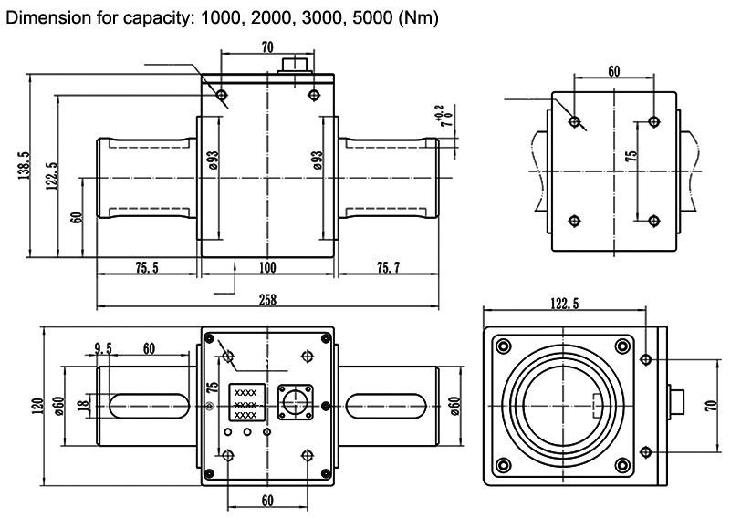
6. Dimension for capacity 10000~20000 Nm (Basic Thread: 120*80, 4-M12 depth 25)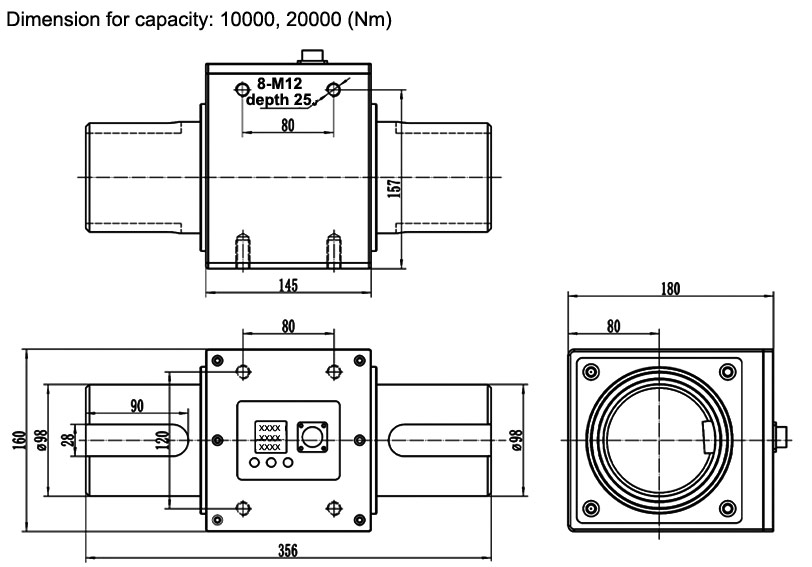
All torque sensors and repair services provided by ATO Torque Sensor are covered by a limited warranty against defective material and workmanship for a period of one year from date of original purchase. Contact ATO for a complete statement of our warranty. Mechanical damage to equipment due to improper use is not covered by warranty. Electronic circuitry failure caused by the introduction of unregulated or improper excitation power or electrostatic discharge is not covered by warranty.
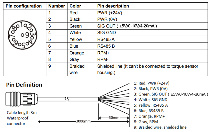
For proper electrical connections, refer to the installation drawing for the digital torque sensor. Construct the interconnect cable from high-quality shielded instrumentation cable. Various cable assemblies are available through ATO Torque Sensor. Make sure to tighten the cable connector to the sensor. For installation in dirty, humid, or rugged environments, it is suggested that the connection be shielded against dust or moisture with shrink tubing or other protective material. Strain relieving the cable/sensor connection can also prolong cable life. Mounting cables to a test structure with tape, clamps, or adhesives minimizes cable whip.
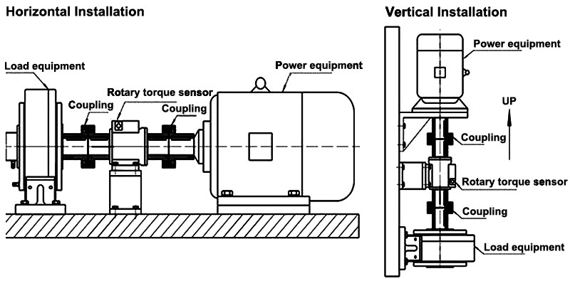
Refer to the dimension drawing supplied for specific outline dimensions and installation details.
The calibration steps are as follows:
- Apply the rated value of torque to the torque sensor and then remove it again.
- Adjust the zero reading accurately.
- Apply a known value of torque to the torque sensor.
- Adjust the displayed reading to the corresponding value.
Plotting a calibration curve:
- Calibrate the torque sensor as described above.
- Apply torque in 1/10 steps up to the full rated value and then remove it again in the same way.
- A delay of at least 30 seconds must be allowed between the individual 1/10 steps so that each reading can stabilize before it is recorded.
Failure of the sensor structure or fasteners used in its installation may cause personal injury and equipment damage. To prevent structure failure, review the extraneous load limits listed on the specification. Extraneous load limits are extraneous side force, thrust and bending moment that may be applied without electrical or mechanical damage to the torque sensor. Do not exceed moment or shear whichever attained first. Measurement inaccuracy and structure damage may result. Install the sensor in a manner that minimizes these loads. In addition, review data from manufacturers of fixtures and fasteners used in the sensors installation to determine if failure might occur due to these loads.