1. Introduction
The torque wrench detection system is unstable, the verification data of the torque wrench is inaccurate, and the problems of inconsistent verification results of the same torque wrench by different equipment are common. The torque wrench detection system includes a torque measuring meter, a reaction torque sensor and a loading device. Many people think that the loading device is only a labor-saving auxiliary device, and too much research is devoted to improving the accuracy and repeatability of instruments and sensors, focusing on electrical research, or linear correction of sensors through software, these methods are not very good to solve system stability problems. At present, there is no relevant standard for the design and production of the loading device, and there is no relevant standardized technical requirement. This paper analyzes the force mechanism of the sensor, analyzes the main reasons for the instability of the system from the perspective of mechanical structure, and improves the repeatability of the system to solve the stability problem of the torque wrench detection system.
2. Theoretical Analysis
When the handle of the torque wrench is subjected to force, in addition to generating torque to the reaction torque sensor, there will also be an equal and opposite reaction force at the connection end of the wrench and the sensor. Such forces within the system perpendicular to the axis of the sensor are called lateral or radial forces.
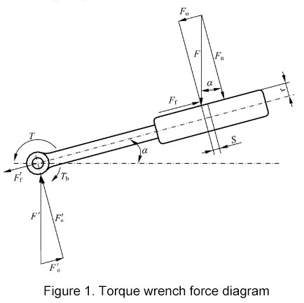
Figure 1 is the force diagram of the torque wrench of the simple screw loading device. The handle of the torque wrench is pulled by the screw, the force is F, and the component force perpendicular to the handle is Fn, and he corresponding reaction force is Fn', Ff' is friction. In the loading device of the worm gear, Fo'=Fo=0, Fn'=Fn=Fo.
In this paper, the loading device of the worm gear is used as a typical structure to analyze the force of the sensor and the reasons for the measurement error caused by its mechanical structure.
2.1 The force and error analysis of the square hole sensor connected directly or indirectly
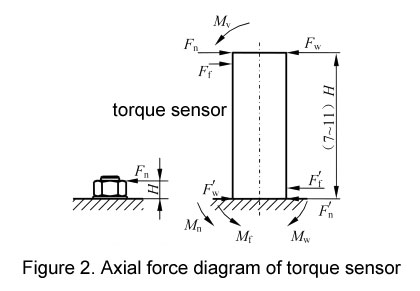
The height of the sensor has an effect on the bending moment caused by the lateral force. Figure 2 is an axial schematic view of the sensor being subjected to a lateral force. The height of the sensor is generally 7~11 times the height of the nut. Assuming that the height of the nut is H, the height of the corresponding sensor is (7~11) H, which means that the bending moment component induced by the sensor is larger than the actual working condition of the nut measured several times. This directly leads to differences in the measured values of sensors with different heights, especially when a long adapter is connected between the sensor and the torque wrench. M in the figure is the bending moment component generated when the handle of the torque wrench is higher than the horizontal plane, which only appears when the operation is improper.
2.2 The stress state and system stability of the sensor connected with the square hole
When a highly accurate and repeatable shaft-to-hole sensor is used to measure the torque of a rotating shaft, there is only a lateral force through the axis (center of the cross-section). Once both ends of the shaft are supported and fixed, the magnitude of the lateral force generated by the assembly stress does not change. If the coaxiality of the supports at both ends is 0, the lateral force is also 0. The measurement data at this point shows that the sensor has good repeatability. However, if the sensor is changed to a square hole and the square tenon of the torque wrench is connected, that the change of the force transmission method causes a great change in the force state of the sensor, even if the square tenon of the wrench and the sensor are coaxial When the degree is 0, the effect of the lateral force cannot be avoided (in fact, the torque is transmitted by the lateral force Fw), and error components is also increased, such as Tn, Tf, Mn and Mf. Therefore, the measurement of torque wrenches with this type of sensor is not as stable as the measurement of rotating shafts. Four of the eight system internal forces can be zero, and there are still four that will generate torque and bending moment, which will affect the accuracy and repeatability of the system. This is also the reason why the coaxiality of the square tenon and square hole sensor is not good when the torque standard machine is installed, which will affect the repeatability. Therefore, ignoring these system internal forces, it will be difficult to improve the stability of the detection system.
3. Methods to Reduce Measurement Error Introduced by Mechanical Structure
3.1 Nonlinear correction
Using software for nonlinear correction can achieve the purpose of relatively stable measurement data, but the measurement error caused by lateral force is covered up, and some indications displayed by the instrument are not the real load received by the sensor, which believed that the sensor has good bending moment performance. Once the measuring point is not above the corrected point or the sensor is connected to another torque meter, its error and measurement instability will be highlighted.
3.2 Improve machining accuracy
The reasons for the errors discussed above all stem from the shape structure of the sensor and the mechanical structure of the loading device. Improving the coaxiality of the reducer, sensor and various coupling parts, improving the accuracy of the wrench and improving the rigidity of the handle, improving the rigidity of the loading device, and taking measures to reduce Tf are all conducive to reducing the bending moment M (Mn, Mf), to improve the repeatability of the detection system.
3.3 Pure torque
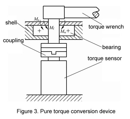
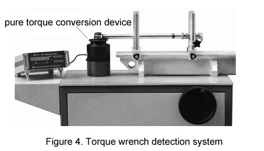
In order to effectively eliminate or minimize the influence of the bending moment M caused by the lateral force on the sensor, the mechanical structure of the loading device must be changed. As shown in Figure 3, a housing with sufficient rigidity is designed to cover the commonly used sensor, a bearing is installed above the sensor, and the torque wrench applies a load to the sensor through the coupling, and the force state of the sensor changes greatly at this time. The various bending moments received by the sensor in Figure 2 are transferred to the bearing and housing parts in Figure 3. This is because the bearing and housing are subjected to various lateral forces and the bending moment M caused by them, and the force transmitted to the sensor is only torque. Such an independent mechanical structure is called a pure torque conversion device, see Figure 4 The magnitude of the bending moment caused by the force is independent of the height of the sensor, and the bending moment of the nut shown in Figure 2 is no longer magnified to be measured, and these bending moments are no longer an error-inducing component. This will load the sensor The state is closer to the working state of the nut tightening process.
When the calibration lever is used to verify this kind of square hole and tenon sensor, the force state of the sensor is roughly, only T is less. Through the reasonable design of the loading device, T, can be reduced to a minimum. A pure torque converter is installed on the loading device, and the sensor for torque wrench only bears pure torque, which is equivalent to using a torque standard machine to verify the torque wrench. The load state of the sensor on these two devices is almost the same, so the value transmission is more accurate It can truly reflect the performance of the torque wrench.
4. Measurement Comparison
After the pure torque converter is installed on the loading device, the torque wrench drives the sensor with pure torque (or the sensor outputs pure torque and drives the torque wrench through the coupling). Point multiple measurements and compare the difference values; shake the sensor and its connecting parts gently before or after each measurement, and re-clamp the wrench after each measurement to simulate the process of the sensor being loaded and unloaded and operated by different people.
Torque wrench handle support:
Unsupported, horizontal support.
Measuring tools:
Digital torque wrench, the accuracy is better than 0.5%FS, the maximum range is 70 Nm.
Testing equipment:
- System A, the loading device is equipped with a pure torque converter, the overall accuracy of the meter and sensor is better than 0.3%, and the measurement points are: 70 Nm (A70 in Figure 5) and 40 Nm (A40. and A40b in Figure 5).
- System B, the comprehensive accuracy of the meter and sensor is better than 0.3%, the measurement point: 70 Nm (B70 in Figure 5).
- System C, the comprehensive accuracy of the meter and sensor is better than 0.25%, the measurement point: 70 Nm (C70 in Figure 5).
Figure 5 is a graph showing the difference between the value of the wrench and the value of the detection meter. The measurement data of the system A with the pure torque converter installed has a small fluctuation, the measurement data obtained by the system B has a relatively large fluctuation, and the measurement data obtained by the system C has the largest fluctuation.
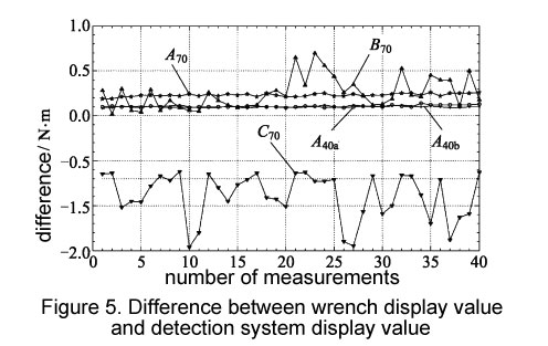
The detection system A is completed by two groups of operators at different times, and A70, A40 and A40b 3 polylines are obtained. Among them, the detection of A70 and A40a polylines are completed by senior metrology engineers who verify the wrench, and the detection of A40b is completed by three metrology engineers who are unfamiliar with this operation and have not yet established a standard. A40a and A40b, these two broken lines measured by different people almost completely coincide, indicating that after using a pure torque converter, the torque detection system has extremely high measurement stability and can exclude the influence of human factors.
The accuracy of the sensor of system C is better than 0.25%. The data fluctuation range of the same wrench detected by this device is more than ten times that of system A (see Table 1), and its repeatability is the worst in the comparison group. The reason is that the sensor connection method of this equipment is seriously flawed. The torque wrench rotates around the sensor and also rotates around the reducer. There are changes after clamping, the torque caused by these lateral forces changes with the changes of these force arms, and the bending moment also changes, resulting in unstable measurement data and excessive measurement errors. It means that the accuracy of the sensor is not high, the detection system error is small, and the system performance can be stable.
| System | Error curve | Measurement value/Nm | Error/Nm | Relative error/(%) | Repeatability/(%) |
| A | A40a | 40 | 0.05 | 0.12 | 0.12 |
| A | A40b | 40 | 0.04 | 0.10 | 0.10 |
| A | A70 | 70 | 0.07 | 0.10 | 0.10 |
| B | B70 | 70 | 0.68 | 0.97 | 0.97 |
| C | C70 | 70 | 0.84 | 1.20 | 1.22 |
The comparison results show that the bending moment inside the detection system installed with the pure torque converter loading device cannot act on the sensor, and the repeatability of the detection system can be optimized 10% of equipment.
5. Conclusion
In the process of calibrating the torque wrench, the main reason for introducing the detection error component from the mechanical structure is not elusive, and the force vector diagram of the sensor is drawn at a glance. It can clearly reveal the source of errors and the measures that should be taken, and can also quantitatively analyze the internal forces of each system that the sensor is subjected to, which has guiding significance for the design and manufacture of sensors, torque wrenches and loading devices.
The combined accuracy or uncertainty of sensors and instruments is not equal to the systematic accuracy or uncertainty of torque detection equipment. After decades of research and technological development, the accuracy of torque measuring meters has increased from 1% to 0.01% or even 0.001%, and the accuracy of torque sensors has increased from 2% to 0.1% or even 0.01%. Older loading devices are the largest source of systematic error. The pure torque drive sensor has a very significant effect on improving the stability of the system.