Reaction Torque Sensor Dual Flange 20 Nm to 10000 Nm

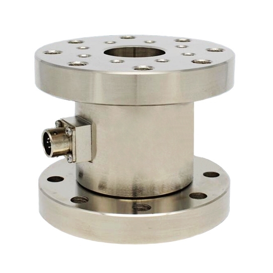
Reaction torque sensor for static torque measurement, 20 Nm/50 Nm/100 Nm/500 Nm/2000 Nm/10000 Nm range, double-flange structure without mounting base, easy to install.
- Torque sensor with strain gauges
- Flange to flange structure
- 0.2%FS non-linearity, 0.05%FS hysteresis
- Measurement of forward and reverse static torque
- Suitable for laboratory use and quality control
Specification
SKU | ATO-TQS-S01 |
Shipping weight | 2~18kg |
Capacity range | 0-1 Nm ~ 0-10000 Nm |
Output signal | DC 0-20mV, or equip torque sensor amplifier ATO-LCTR-OAR for output signal DC 4-20mA, DC 0-5V, DC 0-10V, RS485 |
Sensitivity | 1.0-2.0mV/V |
Zero balance | ±2%FS |
Non-linearity | 0.2%FS |
Hysteresis | 0.05%FS |
Repeatability | 0.05%FS |
Creep | 0.05%FS/30min |
Temperature drift on zero | <0.05%F.S/10℃ |
Temperature effect on output | <0.05%F.S/10℃ |
Operating temperature | -20℃~+80℃ |
Humidity | 0~90%RH |
Impedance | 750Ω |
Insulation resistance | ≥5000MΩ/100VDC |
Stability | 0.3%FS/year |
Safety overload | 120%F.S |
Ultimate overload | 150%F.S |
Excitation voltage | DC 5-15V |
Material | Alloy steel |
Protection class | IP65 |
Electrical connection | 5 pin circular connector (Packing included) |
Cable length | 3m (Φ5mm) (Packing included) |
Wiring | EXC+: Red, EXC-: Black, SIG+: Green, SIG-: White |
Dimensions
Capacity | Dimension (mm) | |||||||
ΦA | B | ΦC | ΦD | ΦE | ΦF | N | G | |
5~50 Nm | 69 | 65 | / | 41 | 6.5 | 57 | 6 | 12 |
100~300 Nm | 69 | 65 | 22 | 41 | 6.5 | 57 | 6 | 12 |
500~1000 Nm | 98 | 80 | 30 | 60 | 8.5 | 80 | 8 | 15 |
2000~5000 Nm | 125 | 96 | 45 | 79 | 13 | 105 | 8 | 20 |
10000 Nm | 160 | 120 | 60 | 95 | 17 | 130 | 8 | 30 |
All torque sensors and repair services provided by ATO Torque Sensor are covered by a limited warranty against defective material and workmanship for a period of one year from date of original purchase. Contact ATO for a complete statement of our warranty. Mechanical damage to equipment due to improper use is not covered by warranty. Electronic circuitry failure caused by the introduction of unregulated or improper excitation power or electrostatic discharge is not covered by warranty.
For proper electrical connections, refer to the installation drawing for the torque sensor, and the wiring drawing for the reaction torque sensor transmitter/amplifier used. Construct the interconnect cable from high-quality shielded instrumentation cable. Various cable assemblies are available through ATO Torque Sensor. Connect one end of the cable to the sensor connector and the other end to the sensor transmitter/amplifier. Make sure to tighten the cable connector to the sensor. For installation in dirty, humid, or rugged environments, it is suggested that the connection be shielded against dust or moisture with shrink tubing or other protective material. Strain relieving the cable/sensor connection can also prolong cable life. Mounting cables to a test structure with tape, clamps, or adhesives minimizes cable whip.
Refer to the dimension drawing supplied for specific outline dimensions and installation details.
Shunt Calibration Steps
- Connect the torque transducer to an appropriate torque sensor transmitter and allow adequate time for the system to stabilize.
- Apply a full-scale, N.I.S.T. traceable, mechanical input (or torque) to the transducer.
- Adjust the torque sensor transmitter’s gain or span controls, as required, to obtain a full-scale electrical output signal, and/or numeric display that represents the applied, mechanical input quantity.
- Remove the mechanical input (or torque).
- Place the shunt calibration resistor across an appropriate leg of the Wheatstone Bridge as discussed above.
- Record the value of the signal conditioner’s output signal and/or numeric display. This value is the shunt calibration value, or equivalent torque.
- It is important to note that the shunt calibration value is specific for the particular shunt resistor used. This value, and the particular resistor, are now matched to the transducer and form a basis of the transferable shunt calibration.
Failure of the sensor structure or fasteners used in its installation may cause personal injury and equipment damage. To prevent structure failure, review the extraneous load limits listed on the specification. Extraneous load limits are extraneous side force, thrust and bending moment that may be applied without electrical or mechanical damage to the torque sensor. Do not exceed moment or shear whichever attained first. Measurement inaccuracy and structure damage may result. Install the sensor in a manner that minimizes these loads. In addition, review data from manufacturers of fixtures and fasteners used in the sensors installation to determine if failure might occur due to these loads.