There are many types of torque sensors. If only based on the type of torque, the torque sensors on the market can be divided into static torque sensors and dynamic torque sensors. This static means that the measuring elastomer of the sensor does not participate in relative motion. While the measurement of dynamic torque, the elastic body generally participates in relative motion (mainly rotation). Because of relative motion, the overall design requires higher lead/signal processing and mechanical connection.
But there are some special torque sensors designed to measure dynamic torque in a static way. Some dynamic torque sensors can measure both dynamic torque and static torque. Therefore, this article will carefully explain the classification of torque sensors according to the measurement principle.
Comprehensive analysis of various torque sensors developed and developed at home and abroad, it is mainly divided into potentiometer type torque sensor, metal resistance strain gauge torque sensor, non-contact torque sensor, high-performance wireless torque sensor, digital torque sensor, etc.
1. Potentiometer Type Torque Sensor
Potentiometer torque sensors can be mainly divided into rotary arm type, double-stage planetary gear type, and torsion bar type. Among them, the torsion bar measurement has a simple structure and relatively high reliability, and was widely used in the early days.
The torsion bar torque sensor is mainly composed of torsion bar spring, angle-displacement converter and potentiometer. Because the torsion bar torque sensor is a contact measurement method, the friction generated during operation makes it easy to wear and affect its accuracy, and will be phased out.
2. Metal Resistance Strain Gauge Torque Sensor
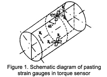
The sensor torque measurement adopts strain electric measuring technology. A measuring bridge is formed by pasting a strain gauge on the elastic shaft. When the elastic shaft is slightly deformed by the torque, the resistance value of the bridge will change, and the change of the resistance of the strain bridge will be converted into the change of the electrical signal to realize the torque measurement.
The sensor is composed of elastic shaft, measuring bridge, instrument amplifier and interface circuit. The elastic shaft is a sensitive element, which produces maximum compressive stress and tensile stress in the directions of 45° and 135°, and bears equal principal stress and shear stress at this time.

The measurement bridge can use semiconductor resistance strain gauges and connect them to form a differential full bridge, the output voltage of which is proportional to the torque received by the torsion shaft.
The amplifying circuit adopts the amplifying circuit for instruments, which is composed of amplifying circuits for special instruments, and there are also three single op-amp circuits combined. In order to have high precision together, the sensitivity coefficient must be a constant.
For the metal resistance strain gauge torque sensor, the technical key points to be solved are:
- The working area of the elastic shaft should not be greater than 1/3 of the elastic area, and the initial segment should be taken. In order to minimize the hysteresis error, select the largest shaft diameter according to the overload capacity index.
- LM-type silicon diffusion force-sensitive full-bridge strain gauge is used, which has better sensitivity and less nonlinearity.
- Adopt high-precision regulated power supply.
3. Non-contact Torque Sensor
Due to the non-contact working method, the non-contact torque sensor has a long service life, high reliability and is not easy to be worn. The non-contact torque sensor has smaller time delay and is less affected by the deflection and axial offset of the shaft, and has now become a mainstream sensor product for wide application.
The basic principle of the non-contact torque sensor is: the input shaft and the output shaft are connected by a torsion bar, the input shaft has a spline, and the output shaft has a keyway. When the torsion bar is twisted by the turning moment of the steering wheel, the relative position between the spline on the input shaft and the keyway on the output shaft is changed. The relative displacement of the spline and the keyway changes by an amount equal to the twist of the torsion bar, which changes the magnetic induction on the spline. The change of the magnetic induction is converted into a voltage signal through the coil. The high frequency part of the signal is filtered by the detection circuit and only the torque signal part is amplified.
Among the non-contact torque sensors, the most commonly used are strain gauge type, magnetoelastic type, magnetoelectric type, photoelectric type and fiber optic type torque sensors.
3.1 Strain gauge non-contact sensor
The strain gauge non-contact sensor is developed on the basis of the strain gauge contact sensor. It integrates the existing torque measurement technology and methods, and realizes the non-contact torque measurement target through technical improvement and innovation. It uses radio telemetry technology to replace conductive slip rings and brush arms of contact torque sensor that transmits torque information.
3.2 Magnetoelastic torque sensor
This type of sensor is based on the piezomagnetic effect of ferromagnetic materials. Because the permeability of the ferromagnetic material is a structural stress-sensitive parameter, the change of the stress in the rotating shaft will cause the corresponding change of the permeability. And the change of the permeability will lead to the change of the magnetic resistance of the sensor magnetic circuit, which is finally converted into a test coil change in the magnetic flux. The information transformation process is as follows:
M->Δσ->Δμ->ΔRm->ΔV
In the formula: M is the torque. Δσ is the change value of the maximum normal stress on the surface of the measured shaft. Δμ is the change value of the magnetic permeability of the measured shaft. ΔRm is the change value of the magneto resistance of the measured shaft. ΔV is the change value of the sensor output voltage.
According to this transformation principle, various types of magnetoelastic torque sensors can be made.
3.3 Magnetoelectric torque sensor
The magnetoelectric torque sensor is made according to the principle of magnetoelectric conversion and phase difference. It converts the torque value into an electrical signal with a phase difference, thus realizing the measurement of torque.
3.4 Photoelectric torque sensor
The main components of photoelectric torque sensor are light source and photoelectric element. When the drive shaft is stressed, the photoelectric element converts the light intensity change obtained by the light source into the output pulse current change, and the torque measurement is realized by measuring the current change.
3.5 Fiber optic torque sensor
It is mainly composed of polarizer, reflective polarizer, lens, optical disc, optical fiber, frequency meter and phase meter. It uses an optical fiber as a probe to receive the reflected light, and then calculates the magnitude of the torque based on the shaft spring constant and phase difference.
4. High-performance Wireless Type
The high-performance wireless torque sensor combines the sensor with wireless communication technology to realize the wireless transmission of data. After the torque electric signal is amplified and A/D converted by the signal processing circuit controlled by the single-chip microcomputer, the encoder transmits the collected digital quantity code to the transmitting module for transmission. After the receiving module receives the data, the decoder transmits the decoded data to the single-chip microcomputer, and the obtained torque data value is displayed by the LED. The sensor data acquisition and transmission circuit is composed of torque sensor, signal processing part, single chip microcomputer and wireless transmission circuit. The torque sensor transmits the electrical strain signal generated by the resistance strain gauge to the signal processing circuit. The signal processing part extracts and amplifies the sensor analog signal, and performs analog/digital conversion. The microprocessor is responsible for controlling the work of each part of the system and processing digital signals. Under the control of the microprocessor, the wireless transmitting circuit encodes and processes the collected information data correspondingly by the encoder, and transmits it with the transmitting module. Realize wireless transmission.
5. Digital Torque Sensor
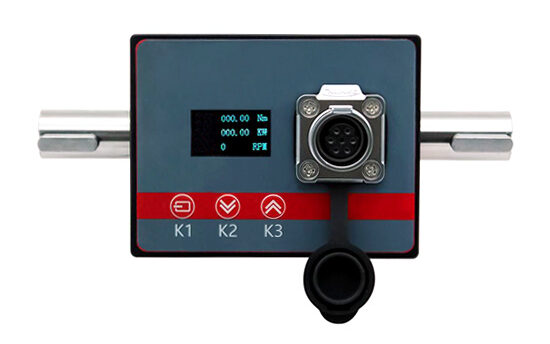
The digital torque sensor is a portable high-performance shaft power measuring instrument for fan and water pump testing and on-site energy efficiency evaluation. The digital torque meter creatively abandons the cumbersome and complex installation process of traditional electromechanical torque sensors, which is difficult to achieve in many field environments, realizes real-time measurement of the efficiency of fans and pumps, and monitors the use of fans and pumps. It provides real-time, real and reliable data for studying the use status of fans and pump motors. It avoids the influence of improper installation of electromechanical torque sensors on test results.

The digital torque sensor can completely replace the shaft power measurement function of the traditional torque sensor, and can obtain the real-time efficiency of the fan and pump motor, providing a rigorous and scientific evaluation method for the energy saving of the fan and pump unit.